

[Click for the tomb-A.fe datafile in a second window.]
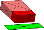
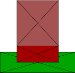
This is the simplest model in the tombstone series. It shows just the chip and the pad, without any solder. The chip is horizontal and some distance above the pad (as placed on solid solder blocks before the solder is melted). The surfaces shown here are actually just for the convenience of the viewer; they will not be used at all in energy or force calculations.
 |
 |
 |
 |
| Oblique view. | View down x-axis. | View down negative y-axis. | View down z-axis. |
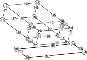
 The wire frame diagram shows the vertices and edges of the datafile.
The numbering may look strange, but that is because when I first set
up the tombstone file, I did pure solder first, then added the pad
and chip displays. I removed the solder for this datafile, hence the
high numbers. This view has the z+ face on top, the x+ face in front,
and the y- face on the left. The orientation of the edges is shown
by the edge numbers being toward the heads of the edges. (The labeled
wire frame pictures are made by
set facet color clear; show edge where original > 1and using the
P 3 PostScript command with responses no grid lines,
no colors, original labels.)
Enter command: z0 := .0015; recalcThe recalc is necessary because changing the value of the variable z0 by itself does not change everything that depends on it, such as the coordinates of vertices on constraints. Note that changing the height this way does not raise the vertices in the middles of the vertical faces. To uniformly raise all vertices, one could define these:
new_z0 := z0
change_z0 := { dz := new_z0 - z0; z0 := new_z0;
               set vertex z z+dz where z > 0;
               recalc;
             }
Now you can raise the chip uniformly by doing
Enter command: new_z0 := .0015; change_z0Note that change_z0 sets z0 before modifying vertex coordinates. That is because changing a vertex coordinate also automatically projects the vertex to its constraints, which should have the new z0.