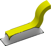
 A gull wing lead is a wire coming from a chip bending horizontally to
make contact with a solder pad on a substrate.
This set of examples models one such joint, beginning very simply and
adding features until a fairly complex model is reached.
The lead has three sections: a horizontal section
above the pad, a circular section rising up at one end, then
a second circular section curving over to horizontal where the
lead enters the chip.
A gull wing lead is a wire coming from a chip bending horizontally to
make contact with a solder pad on a substrate.
This set of examples models one such joint, beginning very simply and
adding features until a fairly complex model is reached.
The lead has three sections: a horizontal section
above the pad, a circular section rising up at one end, then
a second circular section curving over to horizontal where the
lead enters the chip.
The ultimate goal here is to find the equilibrium shape of the liquid solder, and the forces exerted by the solder on the lead. Only translational forces will be done; torques will be left as an exercise for the reader.
The system of units is somewhat ideosyncratic, using the mil-kilogram-second system (1 mil = 0.001 inch), but that is what is used by some in industry and illustrates the point that the Evolver doesn't care what system of units you use as long as you are consistent.
A list of the
various datafiles is below, with brief descriptions. Each datafile has
its own page, which elaborates on the added features and their implementation.
Note that the ordering of the datafiles is tree-like, rather than linear.
The complete set of datafiles and auxiliary command files is available in
gullwing-files.zip
or gullwing-files.tar.
NOTE: These models require Evolver version 2.12 (March 21, 1999) or higher to run. One of the benefits of writing my own software is that if it needs features, I can add them. Some of the datafiles could run on old versions with a little editing, but some definitely need the new features.
It is assumed that you are familiar with the operation of the Surface Evolver at least to the level of the basic Evolver Tutorial examples cube.fe, cat.fe, and mound.fe. Also, it would be well to look first at the Ball Grid Array set of examples first, since that has a much simpler geometry.
The general sequence of steps in modeling a surface is: