The Physics of Microdroplets book cover

This page contains Evolver datafiles for Chapter 1 images. The data files contain evolution scripts (always named "gogo") and scripts for producing EPS files for the book images (always named "run"). The datafiles for this chapter also have scripts (named "run3D" for producing 3D U3D files, which can be used to create 3D PDF files; the scripts also create all the auxiliary files needed and compile a LaTeX wrapper into a viewable 3D PDF file.

The image scripts set the viewing angle with the "view_matrix := ..." command. The particular view matrix used was generated by moving the surface by mouse by hand and then printing out the view matrix with the "print view_matrix" command, and cutting and pasting the result into the command.

Get Surface Evolver

Back to book home page.
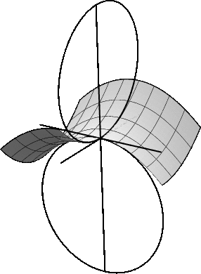

Fig. 1-14: Sectional curvatures of a surface.

Fig_1_14.gif Just a square piece of surface, with one quadrant not shown. The "gogo" command refines and simply sets the vertex z coordinates to the desired function value. Axes are just bare edges. The curvature circles are 1-parameter "boundaries".

Datafile: Fig_1_14.fe


Fig. 1-23: Two droplets linked by precursor film.

Fig_1_23_a.gif The precursor film is implemented by having the two liquid surfaces comprise one Evolver body, so volume moves freely between them. Of course, real precursor films do not permit such free movement, but remember that Evolver is meant to model equilibrium surfaces, not dynamic details.

Datafile: Fig_1_23.fe


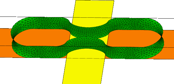
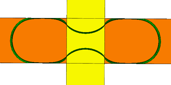
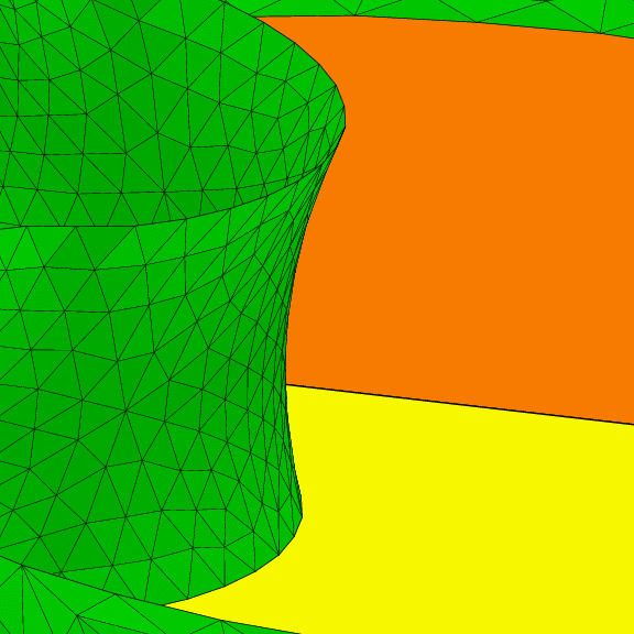
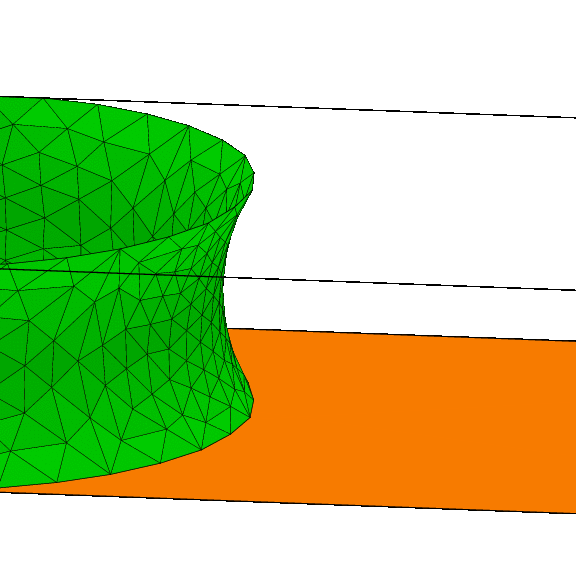
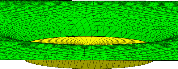
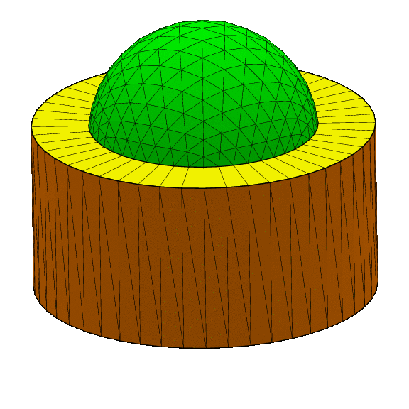
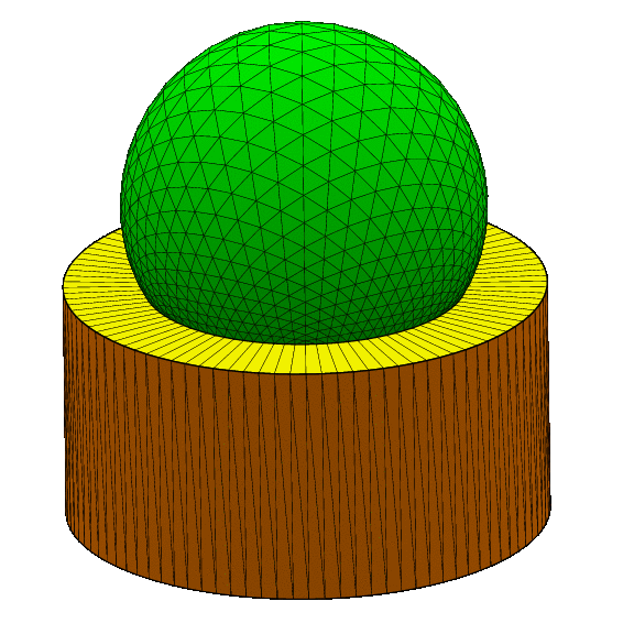
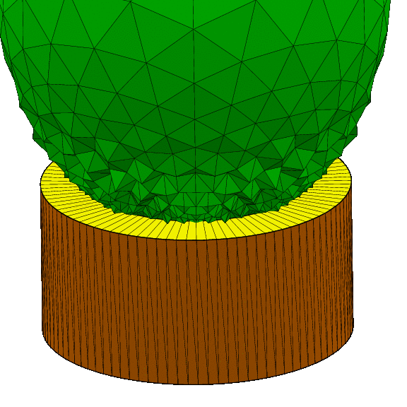
Fig. 1-24: Droplet pinched by a hydrophobic surface.

Fig_1_24_a.gif Fig_1_24_b.gif The yellow hydrophobic band pinches the liquid. The contact lines on the hydrophilic part (brown) are confined by one-sided constraints. Where the contact lines cross the strip edge, there are vertices on constraints, so each contact line edge is on a definite side.

Datafile: Fig_1_24.fe

Fig_1_24_c.gif Fig_1_24_d.gif

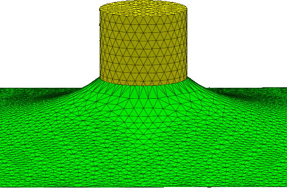
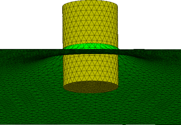
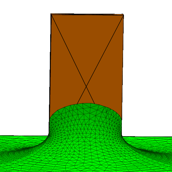
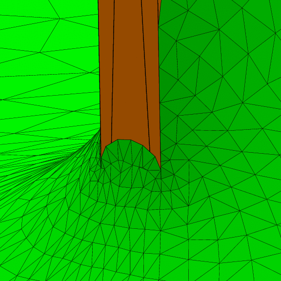
Fig. 1-27: Vertical wire dipped into a fluid.

Fig_1_27_a.gif Fig_1_27_b.gif The contact line on the cylinder is on a separate constraint from the cylinder wall; it is always a good idea to have separate constraints for separate purposes, particularly when one constraint (for the contact line) has an energy integrand (for the contact angle), and the other does not. The vertices on the contact line kept nice spacing without any extra encouragement. Also, note the nice triangulation of the cylinder surface; you have to pay attention to such niceties. This triangulation was prettified by temporarily unfixing it's edges and then equiangulating, after refining.

Datafile: Fig_1_27.fe


Fig. 1-35: Drop flattened by gravity.

Fig_1_35.gif It is interesting to note that a drop flattened by gravity does not have a dimple in the top, no matter how much it gets flattened. This is because the liquid pressure at the topmost point must be nonnegative (maximum principle), so at any lower point the pressure is strictly positive. But at the bottom of a dimple, the liquid pressure would be nonpositive (minimum principle), which would be a contradiction.

Datafile: Fig_1_35.fe


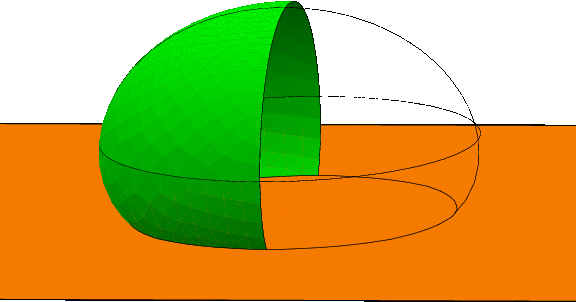
Fig. 1-45: Drop in interface between liquids.

Fig_1_45_a.gif Denser drop that has a high contact surface tension with the carrier liquid, so gravity pulls it down into a dimple.

Datafile: Fig_1_45a.fe


Fig_1_45_b.gif Same densities, but now lower contact tension with the carrier liquid. There is a slight upward bulge in the carrier liquid, contrary to what you might think, due to the finiteness of the extent of the carrier liquid, and the fact that the volume of the carrier liquid has been constrained to be constant, so the intrusion of the drop down into the liquid forces a bulge of the green surface.

Datafile: Fig_1_45_b.fe


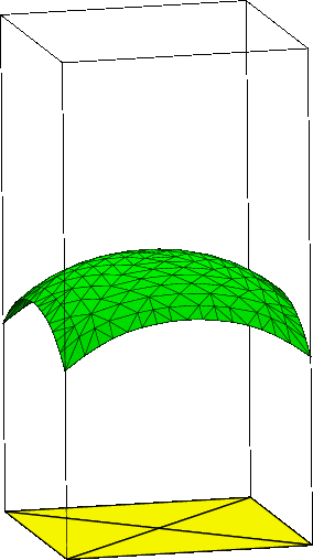
Fig. 1-52b: Coin suspended by surface tension..

Fig_1_52_b.gif This has a liquid surface fixed on a square outer boundary, and fixed to the side of a cylinder in the center. The cylinder contact line is free to move up and down, but it is subject to one-sided constraints keeping it below the top and above the bottom of the coin.

Datafile: Fig_1_52.fe


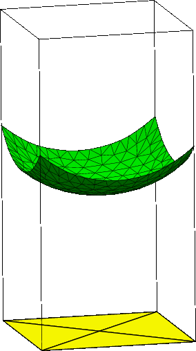
Fig. 1-66: Capillary rise in a square well.

Fig_1_66_a.gif Fig_1_66_b.gif Liquid in a square well, wetting and nonwetting on the sides. Each vertical side is implemented as a level-set constraint, with an energy integrand to calculate the surface contact energy on the walls below the contact lines, so explicit wall facets are not needed.

Datafile: Fig_1_66.fe


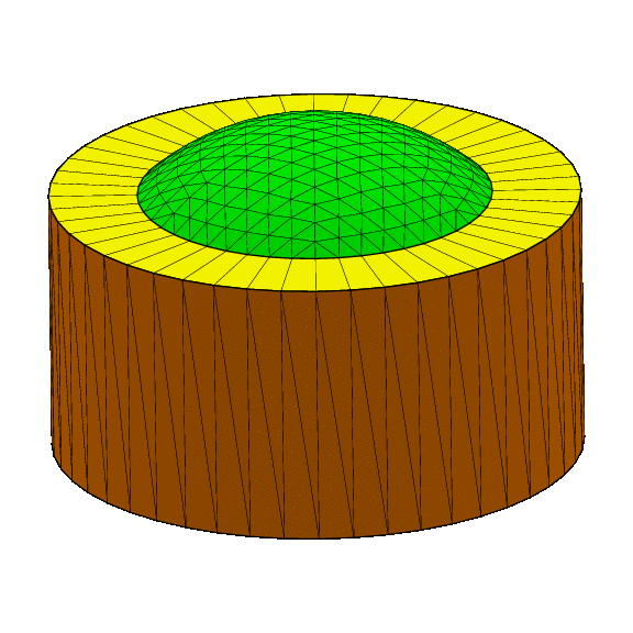
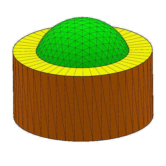
Fig. 1-68: Inflating spherical cap.

Fig_1_68_a.gif Fig_1_68_b.gif Fig_1_68_c.gif The liquid surface has its edge fixed to the inner rim of the top of a cylinder. The pressure is fixed at a certain value, instead of the volume being fixed.

Datafile: Fig_1_68.fe


Fig. 1-69: Exploding spherical cap.

Fig_1_69_a.gif Fig_1_69_b.gif The same datafile as figure 68, just taken beyond a stable hemisphere. The shapes here are not stable shapes, but rather stages in the explosion to infinite volume.

Datafile: Fig_1_68.fe


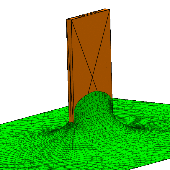
Fig. 1-70: Capillary rise on a Wilhelmy plate.

Fig_1_70_a.gif Fig_1_70_b.gif Fig_1_70-c.gif Liquid surface rising up the outside of a rectangular slab, i.e. a Wilhelmy plate. Each side of the slab is a level-set constraint, with an energy integrand to calculate the surface contact energy below the contact line. Also, there are one-sided constraints to keep the contact line from spreading beyond the edges of the slab. What looks like a groove in the lower left liquid surface is just an artifact of how the meshing looks.

Datafile: Fig_1_70.fe


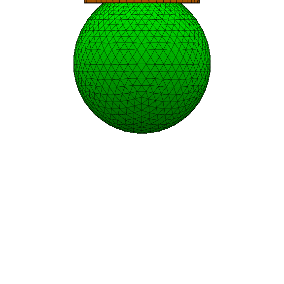
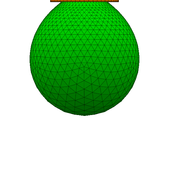
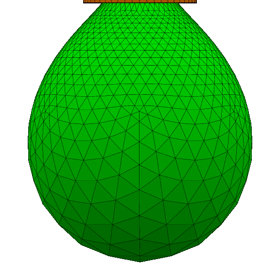
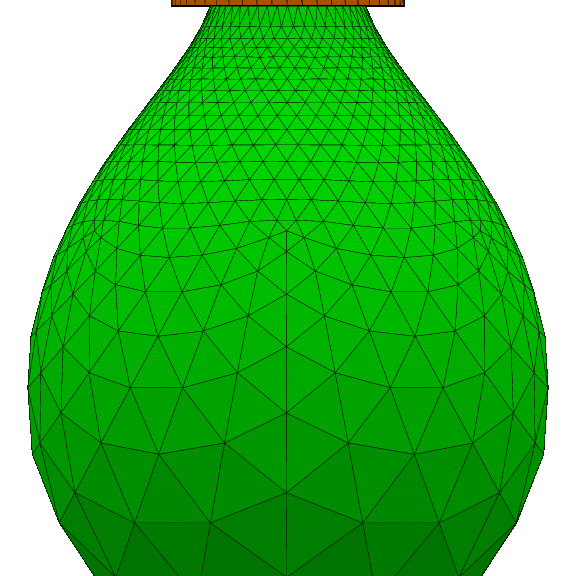
Fig. 1-73: Suspended droplet.

Fig_1_73_a.gif Fig_1_73_b.gif Fig_1_73_c.gif Fig_1_73_d.gif Pendant liquid drop. This is actually the same datafile as fig. 1-68, but with negative gravity and displayed upside down.

Datafile: Fig_1_73.fe


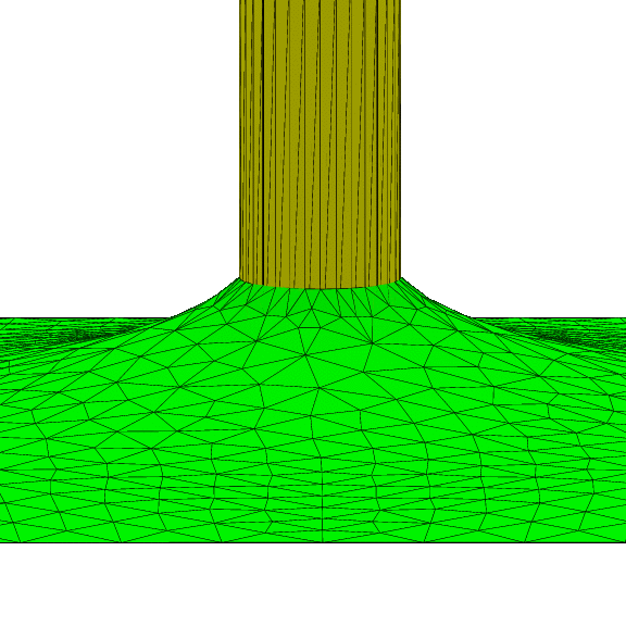
Fig. 1-82: Capillary rise around cylindrical rod.

82/Fig_1_82.gif Liquid climbing up the outside of a cylinder. The contact line is on a cylindrical level-set constraint, with a constraint energy integrand to calculate the contact energy on the cylinder below the contact line.

Datafile: Fig_1_82.fe


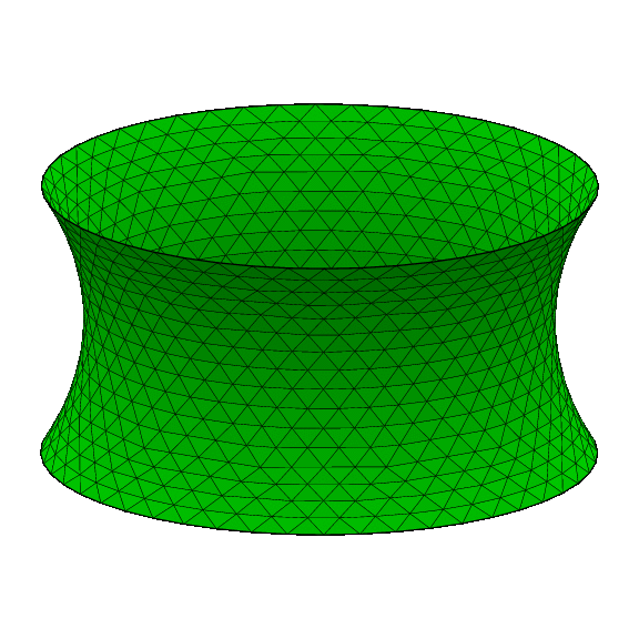
Fig. 1-83: Catenoid soap film.

Fig_1_83_b.gif Catenoid, a soap film between two parallel circular ring. The top and bottom rings are implemented as one-parameter boundaries.

Datafile: Fig_1_83.fe


Back to book home page.